Unreal Animation Framework (UAF)
Assets: Game Animation Sample Project by Epic Games | G2: Mercenaries by Quang Phan
Contents
Introduction
The Unreal Animation Framework (UAF) introduces a different way of building animation systems compared to traditional Animation Blueprints. At first glance, it might feel similar. You still work with animation graphs, blend spaces, and familiar concepts. However, once you start building systems with it, the differences become clear, especially in how modular and data-driven everything is.
In this post, I walk through how I set up a basic locomotion using UAF, how it compares to Animation Blueprints, and some of the issues I ran into while rebuilding a familiar setup. This post is part of my journey exploring UAF. As I worked through the system, I wanted to document what I learned in a practical and structured way, focusing on real implementation rather than theory. I will continue refining this post as I gain more experience, updating it with new insights and improvements over time.
UAF vs Animation Blueprint
In Animation Blueprints, animation logic is typically implemented inside a single graph that handles state transitions, blending, and supporting logic. This approach is powerful and familiar, but as systems grow in complexity, the graph can become harder to manage and extend.
UAF takes a different approach by separating responsibilities into smaller layers and reusable traits. Instead of building and maintaining one large graph, behavior can be extended by adding or modifying individual components. This makes the system easier to organize and more flexible over time.
The key difference is not just in structure, but in how the system scales. Animation Blueprints are often designed around a fixed set of states and transitions, while UAF is built with modularity in mind, allowing systems to evolve without becoming tightly coupled.
In practice, both approaches are valid. Animation Blueprints remain effective for many use cases, especially smaller or well-defined systems. However, UAF provides a foundation that is better suited for building larger and more scalable animation systems.
RigVM
One useful way to think about UAF is that it is not running on the standard Blueprint VM. UAF uses RigVM instead, which is the same execution layer used by Control Rig. RigVM is built specifically for evaluating graph logic through bytecode and dedicated execution memory, making it more specialized than Blueprint’s general-purpose runtime.
That does not mean UAF is the same as Control Rig. Control Rig is a toolset, while RigVM is the execution technology underneath it. UAF reuses that foundation because it is a better fit for modular, graph-based animation systems. Epic also notes that RigVM was chosen because its performance is already much closer to native code than the Blueprint VM, while also running in a sandboxed environment.
UAF in The Witcher 4
To better understand how Unreal Animation Framework (UAF) is used in practice, it is worth looking at the Unreal Engine 5 tech demo for The Witcher 4, presented by CD Projekt Red and Epic Games.
In this demo, UAF is part of a larger animation pipeline designed for a dense open-world environment. The scene runs on a base PlayStation 5 at 60 FPS, while showcasing a large number of animated characters on screen, including areas with hundreds of skeletal mesh agents.
UAF contributes to this by allowing animation systems to be evaluated more efficiently. Instead of running the full animation logic for every character at all times, the system can focus only on what is necessary based on context. This selective evaluation helps reduce overhead and makes it possible to scale animation across many characters.
It is important to note that this result is achieved in combination with other systems, such as Mass AI for crowd simulation and additional Unreal Engine technologies for large-scale worlds.
UAF works as part of this ecosystem, enabling animation to scale alongside the rest of the engine. This example shows that UAF is not just an experimental feature, but a system that is already being explored in real production scenarios for building high-quality, large-scale animation systems.
Plugins to Enable
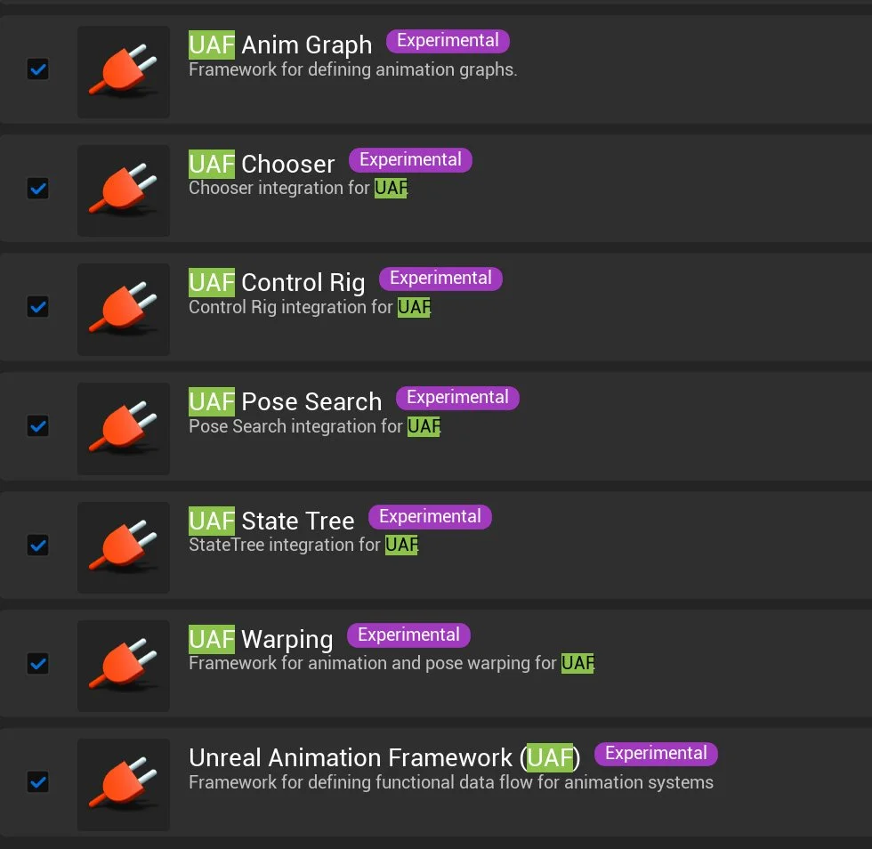
Before working with Unreal Animation Framework (UAF), the first step is to enable the required plugins in the project. The exact set may vary depending on your workflow, but the following are the core UAF-related plugins:
(Open the Plugins window, search for “UAF”, enable the plugins, and restart the editor)
Unreal Animation Framework (UAF)
UAF Anim Graph
UAF Chooser
UAF Control Rig
UAF Pose Search
UAF State Tree
UAF Warping
These plugins expose the UAF workflow inside the Content Browser and enable access to UAF-specific assets such as animation graphs and modules.
Where to Begin?
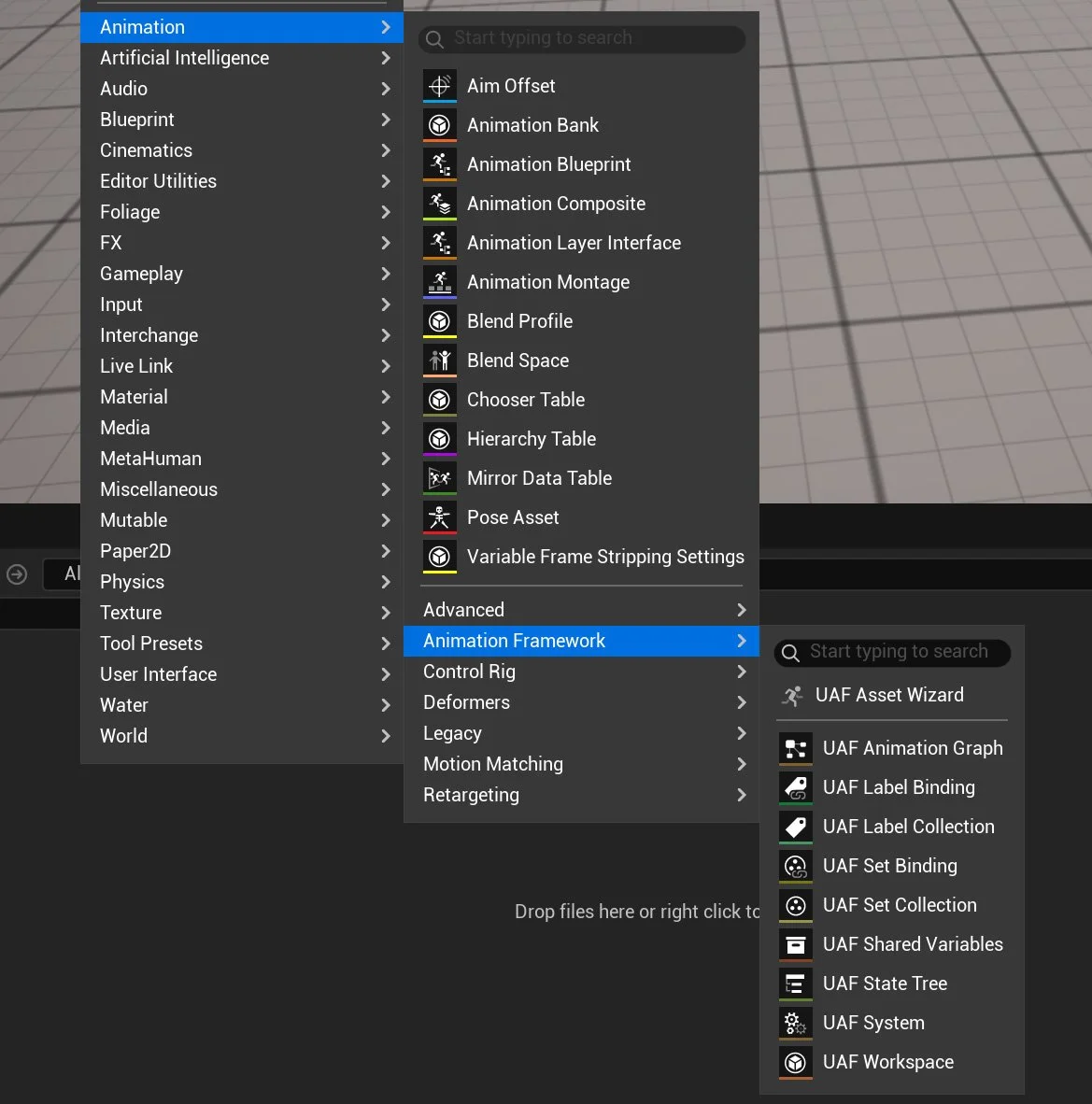
After enabling the required plugins, UAF introduces a new set of assets inside the Content Browser under the Animation Framework category. From here, you can create different types of assets such as:
UAF Workspace
UAF System
UAF Animation Graph
UAF State Tree
A typical starting workflow is:
Create a Workspace: This acts as the main environment where UAF graphs and systems are organized.
Create a System: The system represents the runtime logic that will be attached to an actor.
Create a UAF Animation Graph: This is where animation logic is defined.
Add the graph to the workspace and connect it to the System.
Assign the system to a character using the appropriate component.
This workflow reflects how UAF separates animation logic into modular pieces, instead of relying on a single Animation Blueprint.
UAF Asset Wizard
The UAF Asset Wizard is the main entry point for starting with Unreal Animation Framework. Instead of manually creating and wiring multiple assets, the wizard allows you to quickly generate a preconfigured setup based on a template. By selecting a template (such as the basic boilerplate), choosing a character blueprint, and assigning a skeletal mesh, the wizard automatically creates the core UAF assets, such as the animation graph and system, along with a ready-to-use structure in your project. This significantly simplifies the initial setup and provides a solid starting point for experimenting with UAF without needing to build everything from scratch.
In this example, a simple UAF setup is created with a clear and organized structure. The project contains a dedicated UAF folder along with the following core assets:
A UAF Workspace (UAF_W_Character) used to organize UAF assets
A UAF System (UAF_S_Character) responsible for executing animation logic
A UAF Animation Graph (UAF_AG_Character) that defines the animation behavior
A Character Blueprint (BP_Character) used to run the system in-game
A Skeletal Mesh (SKM_Quinn_Simple) assigned to the character
What the Wizard Configures Automatically in The Blueprint
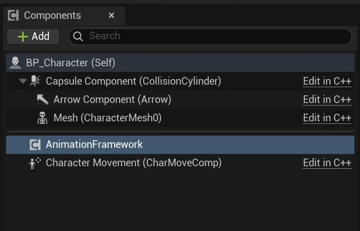
After running the UAF Asset Wizard, several important changes are applied to the generated Character Blueprint to integrate it with the UAF pipeline.
First, a new component called AnimationFramework is added to the character. This component is responsible for running the UAF system at runtime. If you inspect it, you will see that the System field is automatically assigned (for example, UAF_S_Character), which connects the character to the UAF animation logic.
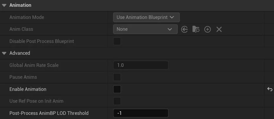
Second, the Skeletal Mesh Component is configured differently from a traditional setup. The standard animation system is disabled (Enable Animation is turned off), meaning the character is no longer driven by an Animation Blueprint. Instead, animation evaluation is fully handled by the UAF system.
The wizard replaces the default animation pipeline with the UAF workflow by:
Adding the AnimationFramework component to execute animation logic
Assigning a UAF System to the character
Disabling the built-in animation system on the skeletal mesh
This setup ensures that all animation behavior is driven through UAF, rather than the traditional Animation Blueprint approach.
Validate that UAF is Correctly Connected
To validate that the UAF pipeline is correctly connected, I started with the simplest possible animation setup: an idle animation.
First, make sure the UAF System is correctly linked to the UAF Animation Graph. Open the generated UAF System (UAF_S_Character), and under Item Label, select Graph. Then assign the Graph field to your animation graph (for example, UAF_AG_Character). This step ensures that the system knows which graph to evaluate at runtime.
In the generated UAF System Graph, the animation flow is split into two stages. The Initialize event prepares the setup by calling Make Reference Pose, which creates a reference pose from the skeletal mesh component. The PrePhysics event handles runtime evaluation: it calls Run Graph to execute the assigned UAF Animation Graph and generate a pose result, then calls Write Pose to apply that pose to the skeletal mesh. In simple terms, the system first prepares the character’s reference data, then evaluates and writes animation every frame.
Next, open the UAF Animation Graph (UAF_AG_Character) and add a Sequence Player node. The Sequence Player is the most basic way to play an animation in UAF. Assign an Idle animation to the Sequence Player and connect it to the graph output.
At this stage, playing the level should result in the character staying in an idle pose. Since the default animation system is disabled on the Skeletal Mesh, seeing the idle animation confirms that UAF is correctly evaluating and driving the animation.
Trait Stack and Why It Matters
One of the key concepts in Unreal Animation Framework (UAF) is the Trait Stack, which defines how animation is constructed and evaluated.
A Trait represents a small unit of animation logic, such as playing an animation, blending poses, or modifying the result. Instead of building all logic inside a single graph, UAF organizes animation as a stack of these modular traits.
The Trait Stack is an ordered collection of traits that are evaluated together to produce the final animation pose. Each trait contributes to the result, either by generating a pose or modifying an existing one.
This approach allows animation to be built in a layered and modular way. For example, a typical stack might include:
A base reference pose
A locomotion trait (idle or walk)
Additional traits for adjustments such as warping or IK
This design provides several important advantages:
Modularity → Individual traits can be reused across different systems
Flexibility → New behavior can be added without rewriting existing logic
Debugging → Issues can be isolated to specific traits
Scalability → Complex animation systems can be built by layering simple components
By stacking traits together, UAF creates a pipeline where each step contributes to the final pose. This makes the system easier to extend, maintain, and reason about compared to traditional animation workflows.
Traits
UAF provides a wide range of traits that can be added to the Trait Stack. These traits define how animation is generated, blended, modified, and controlled.
-
These traits are responsible for generating animation data:
Reference Pose
Provides a base pose from the skeleton. Often used as the starting point for animation.Sequence Player
Plays a single animation sequence. Commonly used for simple animations such as idle.Blend Space Player
Plays a Blend Space using input values like speed or direction. Typically used for locomotion.Motion Matching
Selects the best animation pose from a database based on movement context.Pose Search Result Emulator
Used for testing or simulating pose search results.
-
These traits combine multiple poses together:
Blend Two Way
Blends between two poses using a weight value.Blend by Bool
Switches between two poses using a boolean condition.Blend Layer
Allows blending animations per bone or per layer (e.g., upper body vs lower body).Blend Stack / Blend Stack Core / Blend Stack Requester
Handle layered blending of multiple poses within the Trait Stack.Passthrough / Passthrough Blend
Passes animation through without significant modification.Dead Blending
Handles fallback blending when no valid animation is available.
-
These traits modify existing animation:
Apply Additive
Adds animation on top of a base pose (e.g., breathing on top of idle).Modify Curve
Adjusts animation curves at runtime.Mirroring
Mirrors animation (left/right).
-
These traits improve animation transitions:
Blend Inertializer / Blend Inertializer Core
Smooths transitions using inertial blending.Blend Smoother / Blend Smoother Core / Blend Smoother Per Bone Core
Reduces abrupt changes between animations.
-
These traits control blending weights:
Alpha Input Args / Float Alpha Input Args / Bool Alpha Input Args / Curve Alpha Input Args / Simple Float Alpha Input Args
Provide different ways to calculate blend weights based on input values.
-
These traits adapt animation to gameplay:
Strafe Warping
Adjusts animation to match movement direction.Steering
Modifies animation based on directional movement.WarpTest
Experimental or testing trait related to motion warping.
-
These traits control execution and behavior:
State Tree
Integrates animation with Unreal’s state-based logic system.Call Function
Executes custom logic during animation evaluation.Injection Site
Defines where additional traits can be inserted in the stack.Synchronize Using Groups
Keeps multiple animations in sync (e.g., locomotion cycles).
-
These traits handle events and debugging:
Notify Dispatcher / Notify Filter
Handle and filter animation notifies.Pose History
Stores previous poses, often used for motion matching.
-
These traits help organize animation logic:
Input Pose
Represents incoming pose data.Sub Graph
Allows splitting animation logic into reusable sub-graphs.
-
These traits integrate advanced animation systems:
Control Rig
Enables procedural control of bones inside the animation pipeline.RigLogic
Used for advanced deformation systems (e.g., MetaHuman facial animation).
Adding Walk
Now let’s extend the setup by adding a simple walk cycle to the character.
In this step, I used a Blend Space Player trait and introduced a Velocity variable in the UAF System, which is bound to the Character Blueprint.
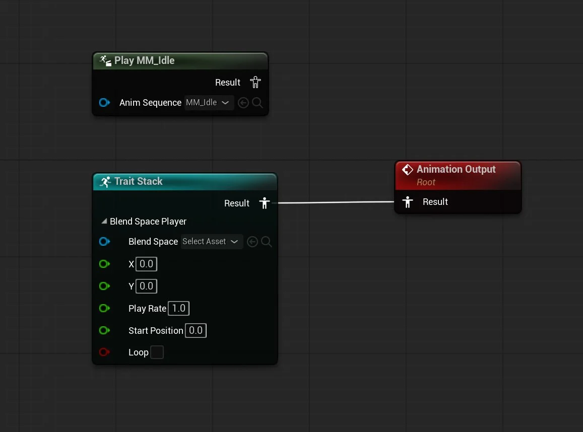
Step 1: Replace Sequence Player with Blend Space Player
First, I disconnected the Sequence Player that was previously used for the idle animation.
Then, I added a Blend Space Player to the Trait Stack.
This trait requires two inputs:
A Blend Space asset
A value representing the character’s speed
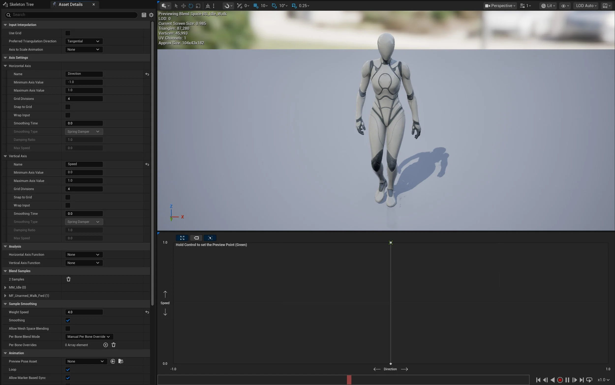
Step 2: Create a Blend Space
Next, I created a simple 1D Blend Space:
Axis: Speed (Vertical / Y axis)
Value 0 → Idle animation
Value 1 → Walk animation
This allows the animation to smoothly interpolate between idle and walk.
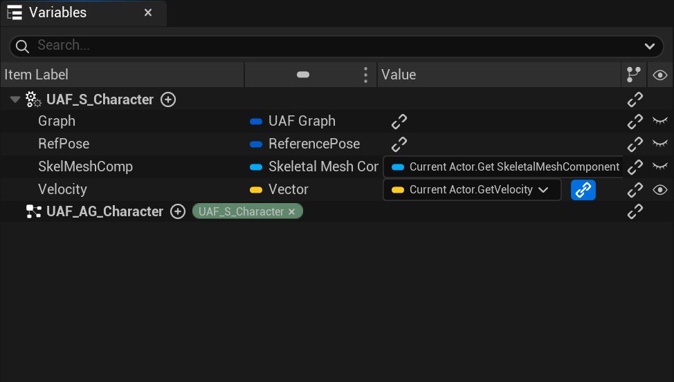
Step 3: Add and Bind Velocity in UAF System
Open the UAF System (UAF_S_Character) and add a new variable:
Type: Vector
Name: Velocity
Then bind this variable to:
Current Actor → Get Velocity
This binding allows the UAF system to receive real-time movement data from the Character Blueprint.
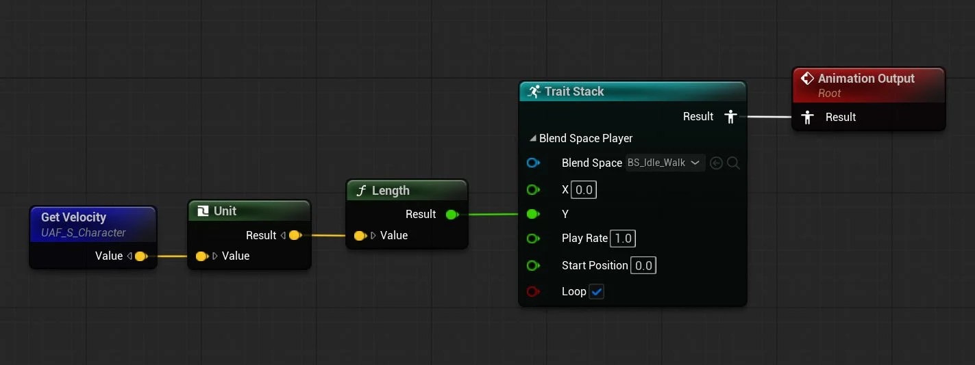
Step 4: Drive the Blend Space from Velocity
In the UAF Animation Graph:
Assign the created Blend Space to the Blend Space Player
Drag the Velocity variable into the graph
Normalize the vector
Calculate its length (magnitude) to get speed
Connect this value to the Blend Space Player input
Result
When playing the level:
At low speed → the character remains in idle
As the character moves → it smoothly blends into walk
This confirms that the Velocity is correctly bound from the Character Blueprint, the UAF system is receiving runtime data, and the Blend Space Player is correctly driving animation
Practical Example
Let’s move into a practical example.
In this section, I will try to re-create the default Third Person Character template, but this time using UAF instead of the traditional Animation Blueprint workflow.
For this example, I am using G2: Mercenaries from FAB.
The goal here is not to build a full production-ready character, but to recreate the same core behavior and logic you would normally expect from the Third Person template, while using UAF as the animation system.
Step 1: Set Up the Character
First, I brought the character asset into the scene and ran the UAF Asset Wizard to generate the basic UAF files, just like in the earlier example.
The wizard created the following assets:
BP_Merc
UAF_W_Merc
UAF_S_Merc
UAF_AG_Merc
After that, I added a Spring Arm and a Camera, then set up the basic Move and Look input actions.
At this stage, nothing fancy is happening yet. The result is simply a capsule-based character that can move around, but without any animation applied yet, as shown in the video.
Step 2: Recreate the Third Person Animation Variables
Now let’s recreate the same variables you would normally see in the default Third Person Character Animation Blueprint.
This is not strictly required when working with UAF, and in many cases there are cleaner, more UAF-native ways to structure your animation data. However, since the goal of this example is to mimic the behavior of the Third Person template as closely as possible, using the same familiar variables makes the comparison much easier.
In the attached screenshot, you can see which variables I added and bound directly to the Blueprint, and which ones will be calculated inside the Animation Graph.
The following variables are bound directly:
ActorRotation
Velocity
CurrentAcceleration
OrientCharacterToMovement
IsFalling
The following variables are calculated in the Animation Graph:
GroundSpeed
Direction
ShouldMove
Step 3: Re-creating the Animation Graph
In this step, I am re-creating the Animation Graph logic using UAF System.
The overall idea is very similar to the original Third Person Animation Blueprint, even though the implementation is a little different. If you look at the two attached images, one shows the original Animation Blueprint graph, while the other shows the UAF graph.
As you can see, I recreated the same core values inside the UAF graph:
GroundSpeed
Direction
ShouldMove
GroundSpeed is generated from the character’s velocity on the XY plane, ShouldMove is used to determine whether locomotion should play, and Direction is calculated manually from the character’s velocity and actor rotation.
One thing I noticed is that there is no built-in Calculate Direction function exposed in UAF in the same way you would use it inside an Animation Blueprint. This is probably not a real limitation, because UAF is designed around a different approach and often relies more on trajectory-based motion rather than the older direction-driven setup.
Still, for this example, I wanted to recreate the familiar Third Person Animation Blueprint workflow as closely as possible. The point here is not necessarily to build the most UAF-native solution, but to use a familiar setup to better understand how the UAF Animation Graph works.
Original Animation Blueprint Graph
New UAF System Graph
Step 4: Building the UAF Anim Graph
In this step, I tried to recreate the original Animation Graph.
As shown in the attached screenshot, I added a locomotion Blend Space and used ShouldMove to blend between the idle and moving state. This keeps the setup close to the familiar Third Person Animation Blueprint structure, but implemented through UAF.
I also added a Control Rig node to handle Foot IK.
While doing this, I noticed one issue: I could not expose the Control Rig variables inside UAF. I am not sure whether this is an intended limitation or a bug, but it is worth mentioning since it affected this setup.
UAF Data Flow
To understand how Unreal Animation Framework (UAF) works, it is useful to look at the full data flow from gameplay to the final animation pose.
At a high level, UAF follows a pipeline where data flows from the Character Blueprint into the animation system:
Input → Binding → System → Graph → Trait Stack → Final Pose
1. Gameplay Data (Character Blueprint)
The process begins in the Character Blueprint, where gameplay logic is evaluated. For example, the character’s velocity is calculated using the engine’s movement system.
2. Binding (Gameplay → UAF)
This data is then passed into UAF through binding.
In this example, the velocity is bound to a variable in the UAF System, making it available to the animation pipeline.
3. UAF System (Execution Layer)
The UAF System is responsible for executing animation logic.
It runs the system graph, which:
Initializes required data (e.g., reference pose)
Executes the assigned Animation Graph every frame
Produces a pose result
4. Animation Graph (Logic Layer)
The UAF Animation Graph defines how animation is evaluated.
It reads bound variables (such as velocity) and uses them to drive animation behavior.
For example:
Velocity → converted to speed
Speed → used to drive a Blend Space
5. Trait Stack (Evaluation Layer)
Inside the graph, animation is built using the Trait Stack.
Each trait contributes to the final result:
Blend Space Player → generates locomotion
Blend traits → combine poses
Modifiers → adjust the animation
The stack is evaluated in order to produce a final pose.
6. Final Pose (Output)
The result of the Trait Stack is a final animation pose, which is then written to the character’s Skeletal Mesh. This is what you see in-game.
UAF is a pipeline where gameplay data flows into a modular animation system that evaluates traits to produce a final pose.
Motion Matching
Motion Matching is a way of playing character animation without relying on a traditional state machine.
In a regular locomotion setup, you usually define states like idle, walk, run, start, and stop, then blend between them based on speed or direction. Motion Matching works differently. Instead of following a fixed set of transitions, it searches through a collection of animations and picks the pose that best matches what the character is trying to do.
For example, if the player starts moving forward, turns suddenly, or comes to a stop, the system looks through its animation data and finds the animation frame that best fits that movement. This makes the result feel more natural, because it is choosing from real motion instead of forcing everything through a small set of predefined blends.
To make this work, you need a few main parts.
First, you need animation data. This is usually a set of locomotion clips such as walking, running, turning, stopping, and pivoting. Those animations are added into a searchable database.
Second, you need information about the character’s movement. Motion Matching does not only look at the current pose, it also cares about where the character is moving and where it is likely to move next. That is why trajectory data is important. The trajectory gives the system a prediction of the character’s movement path, which helps it choose an animation that matches the intended motion.
Third, you need the Motion Matching node or setup inside the animation system so it can evaluate the movement data and query the animation database at runtime.
The main idea is that Motion Matching replaces hand-authored animation transitions with pose selection. Instead of telling the system exactly when to go from walk to stop or from run to turn, you provide good animation data and let the system find the closest match.
In the context of UAF, Motion Matching fits well because UAF already pushes you toward a more modular and data-driven way of building animation systems. Instead of thinking only in terms of states and transitions, you start thinking more about the data the character provides, and how that data drives animation selection.
Trajectory
Trajectory represents where the character is coming from and where it is expected to go next. Instead of only looking at the current pose, Motion Matching also looks at movement over time. That includes recent movement history and predicted future movement. This gives the system more context when choosing the next animation.
A trajectory usually contains samples behind and ahead of the character. The history samples describe recent movement, while the prediction samples estimate the intended path based on player input or controller direction. Together, they help the system understand not just how the character is moving now, but where it is trying to move.
In the UAF System Graph, trajectory data can be generated using either Generate Trajectory from Character Movement Component or Generate Trajectory from Mover. The first is used when the character relies on Unreal’s traditional Character Movement Component, while the second is used with Mover, Epic’s newer movement framework.
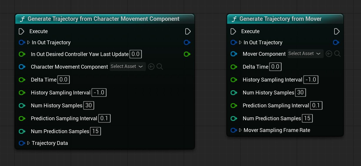
Trajectory Settings
Num History Samples: 30
Defines how many samples are taken from the recent past. With 30 samples, the system can look further back at the character’s movement, which helps capture momentum and direction changes.
Num Prediction Samples: 15
Defines how many samples are generated for the future. With 15 samples, the system gets enough forward information to better react to upcoming turns and movement transitions.
History Sampling Interval: -1
Defines the spacing between past samples. In this setup, -1 appears to rely on the engine’s default behavior instead of using a manually defined interval or maybe it means “use all the animation frames”.
Prediction Sampling Interval: 0.1
Defines the spacing between future samples in seconds. A value of 0.1 means a new prediction sample is taken every tenth of a second, which gives a smooth short-term view of where the character is going.
Game Animation Sample Project (GASP)
While exploring Motion Matching, one useful reference is Epic’s Game Animation Sample Project (GASP). It is a sample project released by Epic Games that demonstrates a full locomotion setup built around Motion Matching, along with the supporting animation systems around it. Epic presents it as a learning resource for studying a modern high-fidelity animation workflow in Unreal Engine.
What makes this project worth paying attention to is that it is not just an old demo. Epic first released it with Unreal Engine 5.4, and they have continued updating it in newer versions, including additional updates in UE 5.7. That makes it one of the clearest public references for how Epic is currently approaching gameplay animation and Motion Matching.
Conclusion
Unreal Animation Framework (UAF) introduces a modular and data-driven approach to animation that differs significantly from traditional Animation Blueprint workflows. Instead of relying on a single monolithic graph, UAF separates responsibilities into clear, well-defined stages.
At a high level, the animation pipeline can be understood as:
Gameplay provides data (such as velocity and state)
Binding connects that data to the animation system
The UAF System executes the logic
The Animation Graph and Trait Stack generate the final pose
This separation allows each part of the system to focus on a specific role, making the overall workflow more flexible and easier to extend.
Throughout this exploration, I focused on understanding how these pieces fit together—from setting up the system using the Asset Wizard, to binding gameplay data, and finally driving animation using traits such as the Blend Space Player.
While UAF is still evolving, it clearly represents a shift toward more scalable and modular animation pipelines. As the system matures, it has the potential to support more advanced workflows such as motion matching, procedural animation, and large-scale character systems.
Limitations and Current State
While UAF introduces a powerful and flexible approach to animation, it is important to understand its current limitations.
Experimental Status
UAF is still evolving, and many features, workflows, and naming conventions may change between engine versions.Limited Documentation
Compared to Animation Blueprints, official documentation and learning resources are still limited, which can make the system harder to learn.Workflow Maturity
Some tools and workflows are not yet as polished or intuitive as the traditional animation pipeline.
Despite these limitations, UAF clearly represents the future direction of animation in Unreal Engine. Its modular and data-driven design makes it well-suited for modern animation systems, especially in large-scale and complex projects.
Next Steps
This post focuses on understanding the fundamentals of Unreal Animation Framework (UAF) and building a simple locomotion setup. However, UAF supports much more advanced animation workflows that go beyond this initial exploration.
In future blog posts, I plan to explore the following topics in more detail:
Motion matching
Pose search
State-driven animation using State Tree
Advanced warping
Procedural animation techniques
These systems build on top of the concepts covered here and represent the next step toward creating more complex and realistic animation pipelines.
References and Useful Links
The following resources were helpful while learning Unreal Animation Framework (UAF). Since UAF is still evolving and not yet widely documented, official sources like Epic Games’ knowledge base are especially valuable.
Unreal Animation Framework (UAF) FAQ
https://dev.epicgames.com/community/learning/knowledge-base/nWWx/unreal-engine-unreal-animation-framework-uaf-faqHow to setup Mover 2.0 + Unreal Animation Framework (UAF) + Motion Matching in 5.7
https://farravid.github.io/posts/How-to-setup-Mover-2.0-+-Unreal-Animation-Framework-(UAF)-+-Motion-Matching-in-5.7/My Understanding of the Unreal Animation Framework in 5.6
https://remremremre.github.io/posts/My-understanding-of-Unreal-Animation-Framework-in-5.6/
Glossary
A
AnimationFramework Component
A component added to a character that is responsible for running the UAF system. It replaces the traditional animation pipeline and drives animation evaluation at runtime.Animation Graph Output
The final pose output of the UAF Animation Graph, which is passed back to the system and applied to the skeletal mesh.
B
Binding
The mechanism used to connect gameplay data (such as velocity or state variables) to the UAF animation system. It allows runtime values from the Character Blueprint to be passed into the UAF System or Animation Graph so traits can use them to drive animation.Blend Space
An asset that blends between multiple animations based on input values such as speed or direction. It is commonly used for locomotion systems like idle, walk, and run.Blend Space Player
A trait used to play a Blend Space inside the UAF Animation Graph. It takes input values (such as speed) and blends between multiple animations accordingly.Blueprint
Unreal Engine’s visual scripting system. It lets you build gameplay and tool logic using nodes instead of writing code, and it is one of the most common ways to create interactive systems in Unreal.Blueprint VM
The virtual machine that runs Blueprint logic at runtime. It is flexible and general-purpose, but it is not as specialized for animation graph evaluation as RigVM, which is why UAF uses RigVM instead.
C
Character Blueprint
A Blueprint class that represents a playable or non-playable character. It typically contains components such as a skeletal mesh and is responsible for running animation systems like UAF.Chooser
A system used to select animations or assets based on conditions or context. It allows dynamic decision-making by choosing the most appropriate animation at runtime.Control Rig
A system in Unreal Engine that allows procedural animation and rigging directly inside the engine. It enables developers to create, modify, and control character animations without relying entirely on external tools.
D
Data Flow
The pipeline through which gameplay data is passed into UAF, processed by the system and graph, and converted into a final animation pose.
M
Motion Matching
A system that selects animation poses at runtime by searching a database for the pose that best matches the character’s current movement and intended direction, instead of relying only on fixed state transitions or Blend Spaces.
O
Output Pose
The final animation result produced by the UAF Animation Graph and Trait Stack, which is applied to the Skeletal Mesh.
P
Pose Search
A system used to find the best matching animation pose from a database. It is commonly used in motion matching workflows to produce realistic and responsive character movement.Pose Search Database
An asset that stores indexed animation data used by Motion Matching. It contains the animations the system searches through at runtime to find the best matching pose.Pose Search Schema
An asset that defines what data Motion Matching uses when comparing poses, such as sampled bones, trajectory data, and related search settings.Pose History
A record of recent pose information used during Motion Matching evaluation. It helps the system compare motion over time instead of looking at only the current frame.
R
Reference Pose
A base pose generated from the skeletal mesh that serves as the starting point for animation evaluation. It is typically created during initialization and used as input for graph evaluation.Rewind Debugger
A debugging tool in Unreal Engine that allows developers to record and replay gameplay frames. It is especially useful for analyzing animation behavior and understanding how systems like UAF evaluate over time.RigVM
A lightweight virtual machine used to execute graph-based logic in systems like Control Rig and UAF. It is designed to evaluate this kind of logic more efficiently than the standard Blueprint VM, which is one reason it makes sense as a foundation for UAF.Run Graph
A node in the UAF System Graph that executes the assigned UAF Animation Graph. It evaluates the graph using the current inputs and produces a pose result.
S
Sequence Player
A node used to play a single animation sequence inside a UAF Animation Graph. It is commonly used as a starting point for testing animation playback.Skeletal Mesh
A 3D model with a skeleton (bones) used for animation. It is the visual representation of a character and is required for playing animations defined in systems like UAF.State Tree
A hierarchical, state-driven system used to manage complex logic and behavior. It can be used to control animation flow, AI behavior, and gameplay states in a structured and scalable way.
T
Trait
A modular unit of animation logic in UAF. Traits can generate, modify, or blend animation data, and are combined together in a Trait Stack to produce the final pose.Trait Stack
An ordered collection of traits that are evaluated together to build the final animation pose. Each trait contributes to the result, making the system modular and extensible.Trajectory
A representation of where the character is moving, including the expected future path. Motion Matching uses trajectory data to choose animations that match movement intent, not just the current pose.
U
UAF (Unreal Animation Framework)
Epic’s next-generation animation system for Unreal Engine, intended to eventually replace Animation Blueprints.UAF Animation Graph
An asset used to define animation logic in Unreal Animation Framework. It contains nodes and connections that control how animations are evaluated and blended at runtime.UAF System
A runtime asset that executes animation logic defined in UAF graphs. It acts as the bridge between authored animation graphs and the character, allowing the system to evaluate and apply animation behavior during gameplay.UAF System Graph
A graph that defines how and when animation logic is executed in UAF. It typically contains events such as Initialize and PrePhysics, and nodes responsible for evaluating and applying animation (such as Run Graph and Write Pose).UAF Workspace
An asset used to organize and manage UAF-related assets such as animation graphs and systems. It acts as a container that brings together different parts of the UAF setup, making it easier to structure and work with animation logic in a modular way.
V
Velocity
The rate of change of an actor’s position over time, usually represented as a vector. In animation systems, the magnitude of velocity (speed) is often used to drive locomotion logic.
W
Warping
A technique used to adjust animations dynamically to match gameplay conditions. For example, it can modify an animation so a character aligns correctly with a target position or object during runtime.Write Pose
A node in the UAF System Graph that applies the final evaluated pose to the Skeletal Mesh. This is the step that makes the animation visible in the game.